Power Supply

material⌗
MATERIAL             CUANTITY       MODEL                         NUMBER
transformer          1              Central derivative            120V - 24V 2A
plug                 1              single phase                  18 or 20 gauge
cable                1 meter        two poles                     509 - 010
breadboard           1              1 block two strips            A22N - 1000 VTA
breadboard cable     2 meters       AWG 22
tip pliers           1
cutting pliers       1
clemas               2              small terminals 2 screws      TRT - 02
clemas               2              small terminals 3 screws      TRT - 03
diode bridge         1              bridge rectifier              KBL-4/200
capacitor            2              ceramic                       0.1 uF 50 V
capacitor            2              Electrolytic                  4700 uF 50 v
capacitor            1              Electrolytic                  2200 uF 50 V
capacitor            1              ceramic                       22 uF 50 V
voltage regulator    1              LM7805
voltage regulator    1              LM7812
voltage regulator    1              LM7912
voltage regulator    1              LM317
resistance           1              1/4 Wats                      180 Ohms
potentiometer        1              5k ohms
photographic paper   2 sheets
phenolic plate       1                                            10 x 10 cm
ferric chloride     1 bottle       MC100                         900 mL
plastic tray         1                                            20 X 15 cm
griddle              1
drill bits           2             Her200 and Her201
drill                1
black marker         1                                            Sharpie
Procedure⌗
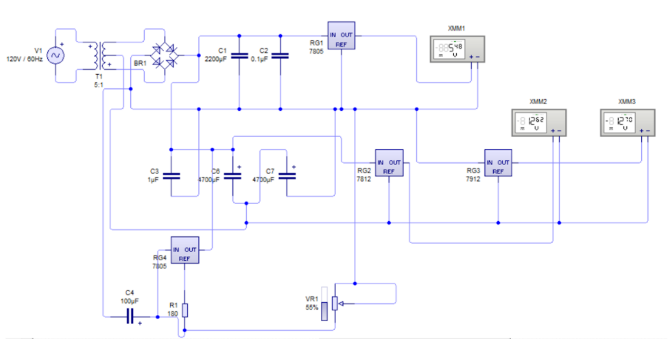
At first, the circuit was generated in the Livewire simulator to check that it worked properly, as shown in the following image:
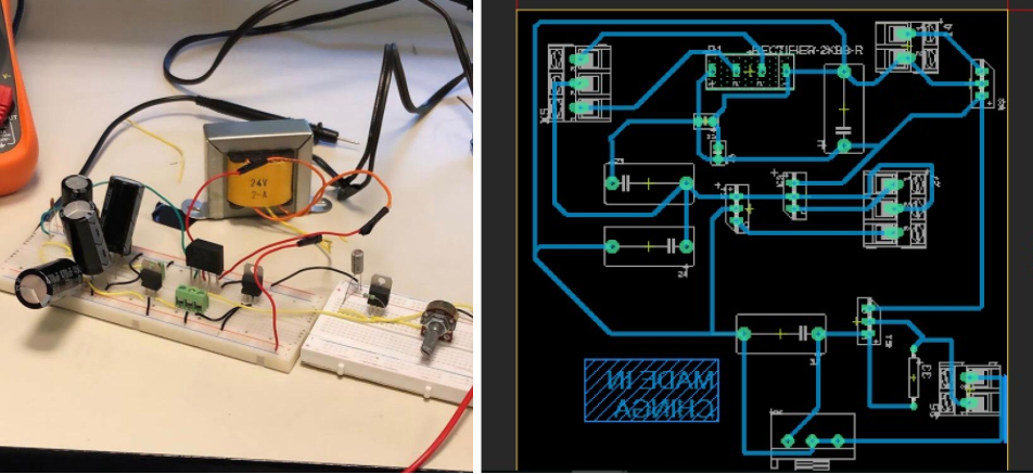
Subsequently, the circuit was generated on the breadboard according to the previously simulated circuit. Once the correct forward voltages were achieved from each of the regulators experimentally, we were able to generate the circuit for printing with Autodesk’s Eagle application, as shown below:
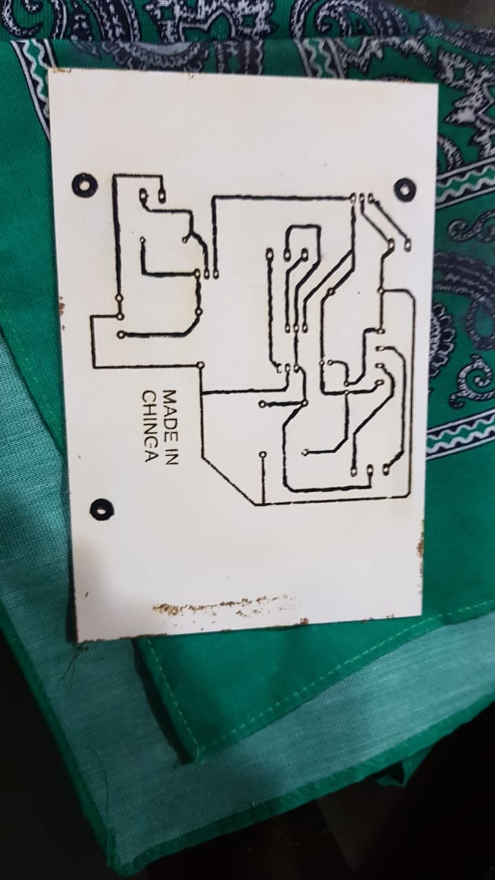
After having arranged the components and wired them so that they do not touch or stick together, we print the circuit on photographic paper. Having already printed the circuit on the photographic paper, it was placed on the phenolic plate and ironed for approximately 30 minutes so that the impression will remain on the phenolic plate. The circuit was immediately marked on the plate with the black Sharpie down, it was started to put it in the plastic tray with 70% ferric chloride and 30% hot water for approximately 20 minutes so that the copper was eliminated in the parts that did not. they connected. After this time, the plate was cleaned with a little thinner so that the pure copper circuit remained on the plate. The result is shown below after following the aforementioned process:
Then, the components were placed in their proper positions according to the simulation that was done in Eagle, the components were soldered and solder was filled in the spaces of the circuit where it was not well reflected to ensure that it would conduct.
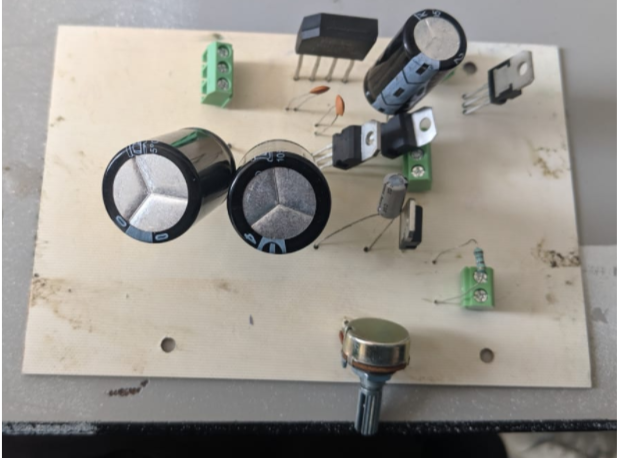
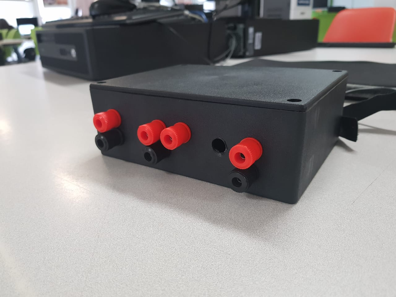
Finally, the board with the components and working properly were put in a plastic box with holes for the respective voltage and potentiometer outputs.