Elevated 4 link mechanism
In 1819 the world was going through a transition that nowadays we call the industrial revolution, the challenge in this era was to make the machines simpler, change most of the systems for others more simpler and easier, mechanisms for converting rotary into linear motion were the ones that were investigated the most, and the accuracy of the system to development was important for the machines that were going to be applied in. In the middle of all this was James Watt, he developed mechanisms that were ingenious and simple, like the Watt linkage, in which the central moving point of the linkage is constrained to travel on an approximation to a straight line. Now a days it is used mainly in the cars suspension. The most shocking of this idea was that he developed it in a letter to Mattew Boulton.
#Methodology
To simulate the mechanism in fig.1 using solidworks and adams and plot the trajectory of point P, for this we have the following measures for each of the links in fig. 1:
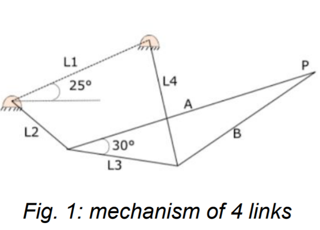
L1 249.50     L3 219.04   A 400
L2 150.205    L4 270      B 237.11
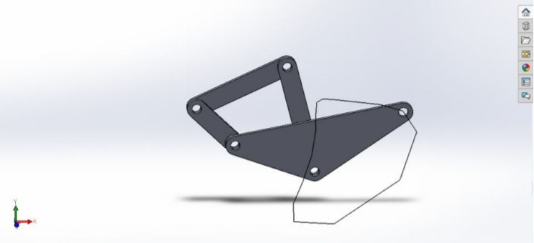
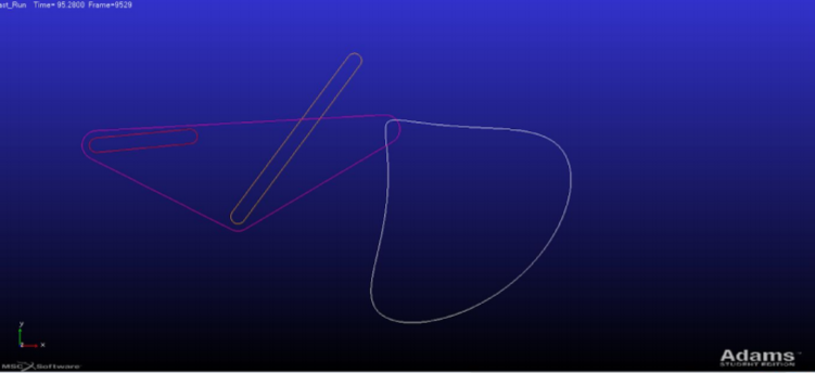
In adams the simplest way to make the mechanism is using markers for reference, while on solidworks we have to make each of the parts separately and then unite them in an assembly, for both of them we have make an animation after plotting the P plot.
#results
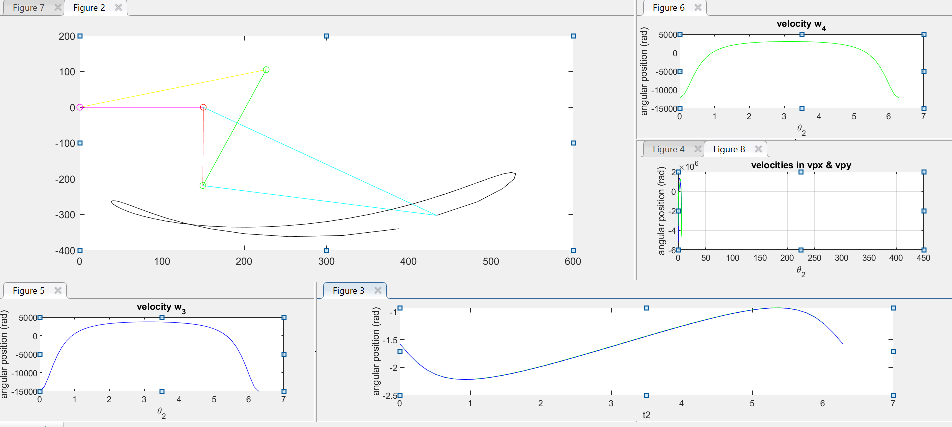
From the simulation in adams (fig. 3), solidworks (fig. 4), Matlab (fig. 5)