Slider Crank

Simulation of a slide crank in ADAMS and MATLAB.⌗
Slider-cranks are a commonly used type of mechanism translating a rotary movement into a linear one, or the other way around. In this lab session, three slider-crank variations were modelled using ADAMS software. Their movements were simulated and analyzed to find the velocities and position for certain input angles. The obtained results were compared to manual computations using the vector loop equations. With these two outcomes, it was attempted to estimate the accuracy of the ADAMS software.
The main applications of it can be found in the industry as in the engines powered by diesel or gasoline, also this type of mechanism has been used and analyzed over time for their advantages as: low cost, few parts, weight and others. The coordinate system to this type of mechanism should make the x-axis and the slider one coincide, so we can associate a vector with each link also we can say that the magnitude of this vector is the length of the link that is being analyzed, the direction of the vector is along the link, so we can conclude that the system made a loop
Methodology⌗
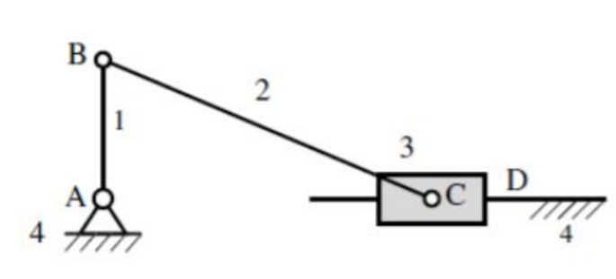
The slider-crank mechanism element AB rotates at constant speed 0.26 rad/s (15°/s) anti-clockwise. Dimensions of elements AB and BC are 120 and 250 mm respectively. To be determined is the velocity of the slider when the angle between AB and the ground, ϕ, equals 45°.
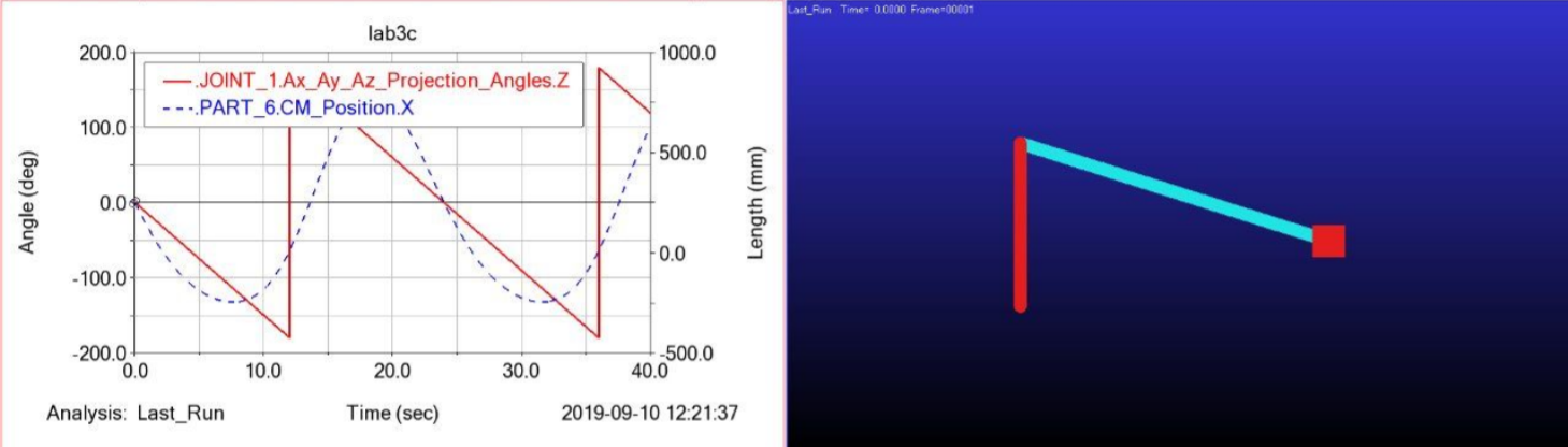
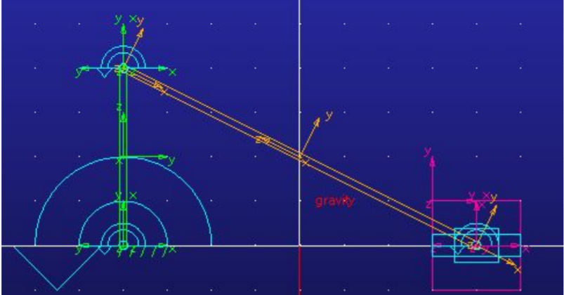
In order to find the velocity of the slider, the mechanism was modelled in ADAMS View. The two bars had a width and depth of 8 and 1 respectively, and lengths as indicated in the description. The material of the bars was left unspecified. Rotational joints were applied at points A, B and C and a translational one between C and the ground. A motion of 15°/s was applied at point A. The movement of the mechanism was simulated for 20 seconds with 5000 steps. After that, the post processor function was used to analyse the movements. To find the exact velocity of point C at the desired input angle, first the x value for which ϕ equals 45° had to be determined by carefully moving over the graph using the arrow keys in the plot tracking function. Subsequently, this x value was checked in the velocity graph to obtain the velocity of point C at that moment.
results⌗
For the input angles of 45°, 27,62° and 90° x positions of respectively 1335,80, 1442,52 and 935 were found.
            45°         27,62°      90°
ADAMS       1335.8      1442.52     953
Matlab      1341.6812   1442.5087   953.9391
Percentage
error       0.44027549  -0.0007834  0.0985414
Table 1: different values for the x-position of the slider as obtained through ADAMS compared to values computed using Matlab
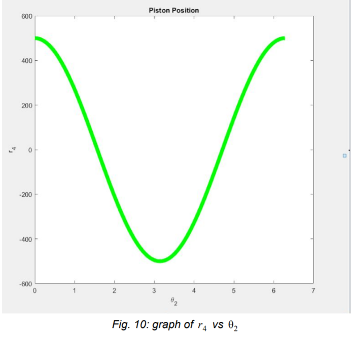
To verify the results, the computations were repeated using Matlab. Subsequently, the percentage error was determined. Two conclusions can be drawn from this comparison: firstly, it is evident that the percentage error is rather large, hence the ADAMS software is likely to be inaccurate. Secondly however, the differences between the percentage errors are remarkably large as well, which is a strong indicator that human mistakes were made: software might make mistakes, but will be more or less consistent all the time. Both of these reflections are reasons not to attach too much value to the results of this project. More research would be needed to figure out where exactly the errors lie, and how the correct results can be found.
trinityscsp,(2013),Crank-Piston Mechanism, Grabcad, Retracted from: https://grabcad.com/library/crank-piston-mechanism-1 Britanica, (n,d),Slider-crank mechanism, Encyclopaedia Britannica, Retracted from: https://www.britannica.com/technology/slider-crank-mechanism Bhupesh Chandrakan, Man Mohan Soni, (June 2015 ),Design and Optimization of Slider and Crank Mechanism with Multibody Systems, International Journal of Science and Research (IJSR) , Retracted from: https://pdfs.semanticscholar.org/a998/e2efb7a894d100caf7668056fc3ba3db7447.pdf